|
|
Zeus Single Ended MOSFET Preamp / Line Driver600 / 150 / 38 Ohm
Test setup. Output to HP8903B for RMS measurements + loading tests.
General Preamp / Line Driver Schematic. Test Configuration
1 kHz THD+N at 2 Vac RMS into 600 ohms = 0.009%
Notes:
Line Driver output = 5.79 volts into 600 ohms - 1 kHz FFT (-3dB) - 0.026% THD
Line Driver output = 4.10 volts into 600 ohms - 1 kHz FFT (-6dB) - 0.018% THD
Line Driver output = 2.90 volts into 600 ohms - 1 kHz FFT (-9dB) - 0.013% THD
Line Driver output = 2.05 volts into 600 ohms - 1 kHz FFT (-12dB) - 0.0093% THD
Line Driver output = 1.45 volts into 600 ohms - 1 kHz FFT (-15dB) - 0.0063% THD
Line Driver output = 1.03 volts into 600 ohms - 1 kHz FFT (-18dB) - 0.0056% THD
Line Driver output = 0.73 volts into 600 ohms - 1 kHz FFT (-21dB) - 0.0038% THD
(All tests 24 bit, 192 kHz sampling, 1 million point transforms.) TransformersT1 - Input Transformer: S&B Type TX-102 TVCSee:
http://www.stevens-billington.co.uk/page102.htm Note for the Mk III version there are 23 output steps: 0, -2, -4, -6, -8, -10, -12, -14, -16, -18, -20, -22, -24, -26, -28, -30, -32, -34, -37, -40, -43, -46 & -52dB. 24th position is to cold i.e. no signal.
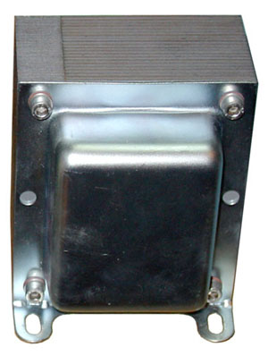
T2 - Output transformer: Susan Parker Type EI120x2", 4x0.71mm, 0.08mm gap.1:1, 2:1 or 4:1 step down. Dual chamber, 4 x 120 turns quad-filar per side, on a 2in EI120 former.
SE Line Driver Output Transformer. Although this size transformer may seem overkill the mosfet is biased at 500 mA so there is some considerable current flowing even when "at rest" and the winding wire used must therefore be of sufficient gauge for this. This output stage will drive headphones down to 32 ohms (use 4 x parallel output windings). Design by: Susan Parker, MIEE. The information contained here may be used to construct one system specifically for personal NON commercial use only. N.B. Personal liability disclaimer applies. This page last modified on: 16th November 2005 All information, drawings and images Copyright © 1995 - 2005 Susan Parker unless otherwise credited. |

All design and other information, drawings and images on this website
are
Copyright © 1992-2010
Susan Parker MIET (unless otherwise credited).
These designs and other information may be used to construct systems specifically for personal NON commercial use only.
N.B. Personal liability disclaimer applies - see T&C.