|
|
Zeus VMOS Line DriverThis line driver is intended for use with a separate preamp and a pair of Zeus power amps. Basic gain is nominally 4 times, although in practise with the under unity follower the actual gain is about 3.5 times. The circuit represents the most basic form of push-pull amplification, and is auto biased without the necessity of a separate bias power supply.
Construction is based on an 8 mm thick piece of aluminium with a couple of angle pieces for the front and rear bezels.
Front view. Small toggle switches are to select Rterm giving low or high impedance input for use with solid state or tube preamps outputs.
Rear view. As this is still a development unit I have not cut down the output transformer leads.
Top view. Overall size is c. 320 x 300mm.
This is the first set of tests made with basic setup on my bench.
Test setup left to right: Sowter 9063e input transformer, VMOS FETs on heatsink, SP Output transformer, 600 ohm load (switchable from 150R to 1K5 in 150 ohm steps).
General Line Driver Schematic (Note: R-term across output of X1 not shown). Test Configuration
1 kHz THD at 2 Vac RMS into 600 ohms = 0.0011%
Notes:
Line Driver output = 4.12 volts into 600 ohms - 1 kHz FFT (-6dB) - 0.0019% THD
Line Driver output = 2.91 volts into 600 ohms - 1 kHz FFT (-9dB) - 0.0012% THD
Line Driver output = 2.06 volts into 600 ohms - 1 kHz FFT (-12dB) - 0.0011% THD
Line Driver output = 2.05 volts into 600 ohms - 19+20 kHz FFT (-12dB) - 0.0210% IMD
Sound Card Loop-back - 1 kHz FFT (-6dB) - 0.0007% THD
Sound Card Loop-back - 1 kHz FFT (-12dB) - 0.0008% THD
Sound Card Loop-back - mute - residual noise and pickup.
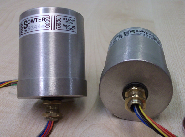
X1 - Input Transformer: Sowter type 9063e
MuMetal can is very important in reducing extraneous emc/rfi pickup. N.B. Although Sowter specify a typical series output -3dB bandwidth of 90 kHz in my configuration I am getting 200 kHz.
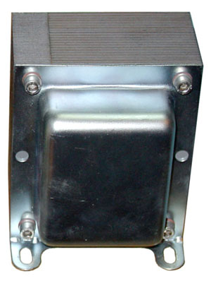
X2 - Output transformer: Sowter type 9940EI120x2", 4 x 0.71mm, 0.08mm gap; 1:1, 2:1 or 4:1 step down. Dual chamber, 4 x 120 turns quad-filar per side, on a 2in EI120 former.
600 ohm Line Driver Output Transformer. Although this size transformer may seem overkill the transformer has a large gap to reduce distortion so many turns are needed for the required inductance. This output stage will drive headphones down to 32 ohms (use 4 x parallel output windings). Design by: Susan Parker, MIEE. The information contained here may be used to construct one system specifically for personal NON commercial use only. N.B. Personal liability disclaimer applies. |


All design and other information, drawings and images on this website
are
Copyright © 1992-2010
Susan Parker MIET (unless otherwise credited).
These designs and other information may be used to construct systems specifically for personal NON commercial use only.
N.B. Personal liability disclaimer applies - see T&C.