|
|
Zeus35 Power AmplifierMy Original Pair of IRFP150 MOSFET Monoblock Amps - Built in 1995
Amplifier Schematic (a reminder of the circuit complexity).
Monoblock Amplifier Front View
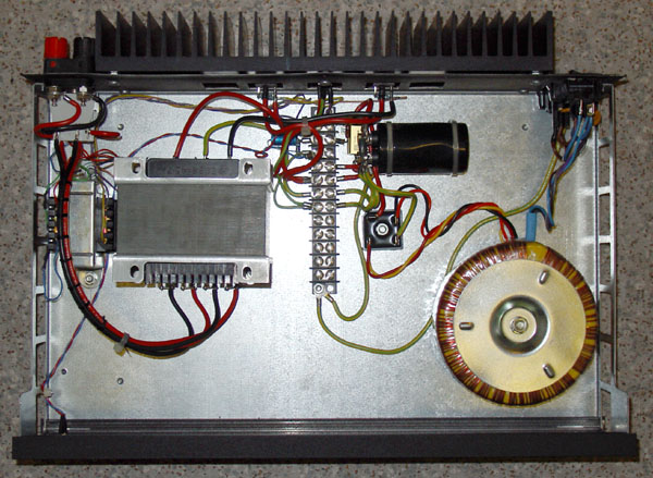
Top Inside View
Rear View - Note 2:1/4:1 Tx switch (RH side).
General Internal Layout
Audio Path Transformers
Heatsink Mounting on Rear PanelNotes:
Testing
|


| Vac RMS | 2:1 Tx - THD+N % | 4:1 Tx - THD+N % |
| 1.00 | 0.123 | 0.094 |
| 1.25 | 0.109 | 0.070 |
| 1.50 | 0.096 | 0.057 |
| 1.75 | 0.089 | 0.049 |
| 2.00 | 0.088 | 0.040 |
| 2.50 | 0.099 | 0.032 |
| 2.84 | 0.118 | 0.031 |
| 3.00 | 0.128 | 0.030 |
| 4.00 | 0.224 | 0.029 |
| 5.00 | 0.369 | 0.033 |
| 6.00 | 0.512 | 0.043 |
| 7.00 | 0.598 | 0.060 |
| 8.00 | 0.646 | 0.086 |
| 9.00 | 0.665 | 0.116 |
| 10.0 | 0.669 | 0.161 |
| 11.0 | 0.664 | 0.542 |
| 12.0 | 0.652 | |
| 13.0 | 0.637 | |
| 14.0 | 0.620 | |
| 15.0 | 0.605 | |
| 16.0 | 0.588 | |
| 17.0 | 0.620 | |
| 18.0 | 0.744 | |
| 19.0 | 0.944 | PSU Supply Limit |
Zeus35 2:1 and 4:1 distortion figures
Note the much lower figures for the 4:1 setting - the trade off is the lower power output.
N.B. These results are similar to but not quite the same as the FFT derived figures.
FFT Tests (2008)
4:1 Op Tx - 1 kHz sine wave, 8 ohm load.
![]()
 |
4 Watt THD @ 1 kHz = 0.0353%
![]()
 |
2 Watt THD @ 1 kHz = 0.0254%
![]()
 |
1 Watt THD @ 1 kHz = 0.0148%
![]()
 |
0.5 Watt THD @ 1 kHz = 0.0154%
![]()
 |
Amplifier ON, residual noise and pickup, 8 ohm load.
The noise above 20 kHz is the switching power supplies in the computer and monitor.
![]()
4:1 Op Tx - 2 Watt (nominal), 8 ohm load.
 |
2 Watt THD @ 20 Hz = 0.2594%
 |
2 Watt THD @ 50 Hz = 0.0532%
 |
2 Watt THD @ 100 Hz = 0.0295%
 |
2 Watt THD @ 200 Hz = 0.0183%
 |
2 Watt THD @ 500 Hz = 0.0149%
 |
2 Watt THD @ 1 kHz = 0.0185%
 |
2 Watt THD @ 2 kHz = 0.0284%
 |
2 Watt THD @ 5 kHz = 0.0642%
 |
2 Watt THD @ 10 kHz = 0.1358%
 |
2 Watt THD @ 20 kHz = 0.2460%
 |
2 Watt THD @ 50 kHz = 1.735% (HP8903B measurement)
![]()
FFT Analysis by WINaudioMLS software
PRO EX Version + 64-bit ultra high precision FFT; 192kHz/24 Bit ASIO support.
Design by: Susan Parker, MIET.
The information contained here may be used to construct one system specifically for personal NON commercial use only.
N.B. Personal liability disclaimer applies.
All design and other information, drawings and images on this website
are
Copyright © 1992-2010
Susan Parker MIET (unless otherwise credited).
These designs and other information may be used to construct systems specifically for personal NON commercial use only.
N.B. Personal liability disclaimer applies - see T&C.